Difference between revisions of "Beehive B100"
(Add images) |
(Add summary description of hardware design.) |
||
| Line 15: | Line 15: | ||
| char_resolution = 80x24 | | char_resolution = 80x24 | ||
| char_resolution2 = 80x12 | | char_resolution2 = 80x12 | ||
| + | | attributes = normal, blink, protected | ||
| refresh_rate = 60 | | refresh_rate = 60 | ||
| refresh_rate2 = 50 | | refresh_rate2 = 50 | ||
| Line 39: | Line 40: | ||
}}</ref> | }}</ref> | ||
| − | == [[Manx]] | + | The B100 includes the following features: |
| + | * Cursor control (up, down, left, right) | ||
| + | * Cursor home | ||
| + | * Cursor position absolute | ||
| + | * Clear from cursor to end of line | ||
| + | * Clear from cursor to end of screen | ||
| + | * Clear screen | ||
| + | * Insert mode | ||
| + | * Blink mode | ||
| + | * Format mode | ||
| + | * Protected fields | ||
| + | * Keyboard enable/disable | ||
| + | * Line send | ||
| + | * Page send | ||
| + | * Auxiliary page send | ||
| + | |||
| + | Normally the terminal operates in a "conversational mode" where keys are transmitted as soon as typed when the terminal is on-line. A switch at the rear of the terminal can put the terminal in "block" mode. In block mode, data is only transmitted when the SEND key is pressed. Format mode allows portions of the screen to be configured as protected. Protected portions of the screen are not transmitted when the SEND key is pressed. When format mode is combined with block mode transmission, the screen is typically configured as a "fill out form", with protected regions used to label the input fields on the form. The user can move the cursor from field to field, entering and editing the data displayed on the screen until correct. The SEND key is then used to transmit the entire unprotected contents to the computer. | ||
| + | |||
| + | = Hardware Description = | ||
| + | |||
| + | The {{PAGENAME}} terminal is quite complex for a discrete logic design. The trend was towards microprocessor based designs in the period following the introduction of the B100. The B100 control circuitry is divided into two main sections: display refresh and receive/transmit functions. | ||
| + | |||
| + | == Display Refresh == | ||
| + | |||
| + | Display timing is driven by a cascade of counters, each divided down from the previous. The main timing chain (oscillator, dot position counter, character position counter, character height counter, and character line counter) defines the configuration of the display on the CRT. There are 30 lines, 6 of which are used for vertical retrace and 24 of which are used to display characters. The 30 lines are composed of 9 scans each. Each scan is composed of 96 character times, 80 for display and 16 for horizontal retrace. Each character block is composed of a 7x9 dot matrix field which contains a 5x7 character matrix for the displayed character. | ||
| + | |||
| + | === Oscillator === | ||
| + | |||
| + | The oscillator is crystal controlled with a frequency of 10.8864 MHz. Two 74H04's are connected in series by a 100 pF capacitor. Each 74H04 has a 1 Kohm feedback resistor around it. A 10.8864 MHz crystal is connected to the input of the first 74H04 to the output of the second. The output of the oscillator is buffered, inverted and fed to the Dot Position Counter. | ||
| + | |||
| + | === Dot Position Counter === | ||
| + | |||
| + | This divide-by-seven counter defines each of the seven dots required to compose one character. The outputs of this four stage counter are labeled DPC1, DPC2, DPC4 and DPC8. The counter actually presets to a count of 10, counts up through the overflow point at 15 to a count of zero, and then presets back to a count of 10. The Dot Position Counter output, DPC8, drives the Character Position Counter. | ||
| + | |||
| + | === Character Position Counter === | ||
| + | |||
| + | The Character Position Counter is composed of two binary type counters that define 96 character times, each being seven dots wide. The output of the Character Position Counter drives the Character Height Counter. | ||
| + | |||
| + | === Character Height Counter === | ||
| + | |||
| + | The Character Height Counter is a standard counter that defines 9 scans of 96 characters each, with each character being seven dots wide. The output of the Character Height Counter drives the Character Line Counter. | ||
| + | |||
| + | === Character Line Counter === | ||
| + | |||
| + | The Character Line Counter is a binary counter that starts at a count of zero and counts to a maximum of 29 for a total of 30 character lines. The final output of this counter runs at the vertical refresh rate. | ||
| + | |||
| + | === Horizontal and Vertical Drive === | ||
| + | |||
| + | The Horizontal Drive is started when the Character Position Counter leaves the video area of the scan and is active for the following 40 character times. The high active output of this flip-flop is sent to the monitor on pin 9 of connector J1. | ||
| + | |||
| + | The Vertical Drive is generated during the time that the Character Line Counter is decoding 26. | ||
| + | |||
| + | === Cursor Location Counter === | ||
| + | |||
| + | The Cursor Location Counter identifies the location of the cursor. This is a count made from the Cursor Line Counter, called CURL, and the Cursor Position Counter, called CURP. These two counters, in conjunction with the ROLL counter, are used to address the memory to determine the entry point of the next character. The cursor location counters are compared with the Character Position Counter and the Character Line Counter to generate the signal called CNTR CURSOR. This signal is used to generate the cursor displayed on the CRT. Also associated with the cursor location counters is the appropriate circuitry to move the cursor up, down, left, right, etc. | ||
| + | A LINE FEED code causes the Cursor Line Counter to increment by one. A CARRAIGE RETURN code clears the Cursor Position Counter. | ||
| + | |||
| + | With the terminal operating in FORMAT MODE, when the cursor is incremented off the bottom line, the cursor automatically wraps around to the top of the display, i.e., the Cursor Line Counter is reset to zero. However, if the terminal is not in FORMAT MODE, the display scrolls whenever the cursor increments from a count of 23. | ||
| + | |||
| + | A scroll is initiated by any of 3 functions if activated when the cursor is on the last line of the display and the terminal is not in FORMAT MODE: | ||
| + | * LINE FEED or Ctrl+J | ||
| + | * CURSOR DOWN or ESC B | ||
| + | * if the cursor is on the last position of the last line: | ||
| + | ** Cursor right | ||
| + | ** Any displayable character | ||
| + | ** Space | ||
| + | |||
| + | === Memory === | ||
| + | The page memory is arranged as 2048 9-bit words: 7 for character data, one for protect and one for blink. Of these 2048 words, 1920 are displayable. The program does not have the capability of displaying or writing into the remaining 128. In order to write data into the page memory from the receiver, the memory address is multiplexed over to the cursor location registers and the signal WRITE is generated. The UART is then reset and is capable of receiving the next character. The page memory output is sent to the character generator input buffer at the proper time to generate the displayable characters. The program has the capability of shutting down the screen refresh for any given to increase the operating time. | ||
| + | |||
| + | === Character Generator === | ||
| + | |||
| + | The Character Generator is a read-only memory (ROM) that is address by the character (in ASCII). The scan configuration of the character indicates the pattern desired on that scan. Five-bit dot patterns are generated which form a portion of a character. The output of the character generator is applied to the parallel-to-serial video shift register. | ||
| + | |||
| + | === Video Shift Register === | ||
| + | |||
| + | The paralle-to-serial Video Shift Register is loaded with data by the low-active signal, DPC8, and is clocked by the main oscillator output. The dots are shifted out, mixed with cursor information, and blanking signals, and applied to the monitor through the CONTRAST control as video information. | ||
| + | |||
| + | == Transmit and Receive == | ||
| + | |||
| + | Processing of received escape sequences is handled by a state machine implemented in a programmable logic array. The state machine has a small set of fixed-function registers for performing the various operations requested by the escape sequences. In some lengthy operations, access to the display memory by the display refresh circuitry may be disabled so the state machine can complete the requested operation without competing for access with the refresh circuitry. This has the effect that the screen will not display stored characters for as long as display refresh is disabled. At the end of the operation, display refresh access is enabled and the display of characters on screen is restored. | ||
| + | |||
| + | === UART (Receiver) === | ||
| + | |||
| + | Data can be received by the B100 from one of two sources: from the I/O interface into the receiver side of the UART, or from the keyboard through the transmit side of the UART to the receive side of the UART. | ||
| + | |||
| + | The UART is driven by a clock generated internally off the main counter chain. No separate oscillator is required. A rotary switch located on the back panel switches the clock rate for operation from 75 to 19200 baud. The time 16 clock is then applied to the transmitter and receiver of the UART. | ||
| + | |||
| + | The EIA line receiver receives data at RS 232C levels and gates them into the UART when the B100 is on-line. Through the same gating, data is brought from the transmit side of the UART. The data is brought into the UART where it is converted to parallel (seven bits) data. | ||
| + | |||
| + | === UART (Transmit) === | ||
| + | |||
| + | The keyboard data lines for bits 1 through 7 are applied to the transmit input data lines along with the seven BUS lines. Also coming from the keyboard circuit is a load signal which triggers the UART to initiate the transmission. As the UART receives the character for transmission, it performs the appropriate parity generation, provides one or two stop bits, divides the X16 clock to get the baud rate, and transmits the character. The character is applied through an EIA RS 232C interface to the computer or modem. Also coming from the UART is output data at a TTL level which is applied to the receiver side of the UART through the previously mentioned logic. The EIA interface includes a Data Terminal Ready signal which indicates the status of the B100 to the computer and a Request to Send signal which indicates that the terminal has data to send to the computer. The Clear to Send line coming from the computer is monitored at the EIA RS 232C interface levels. It is received by a line receiver which converts it to TTL levels and applies it to the UART clock control circuit to control transmission. An optional times 8 clock (TTL levels) is available as part of the interface. The BREAK key is on the keyboard and enables a timer which holds the transmit data line in a spacing condition for a predetermined period of time. | ||
| + | |||
| + | === Block Send Circuit === | ||
| + | |||
| + | The Block Send feature allows the operator to compose a message on the terminal screen and then, by depressing the SEND key, cause the terminal to send the entire message to the computer at the selected baud rate. The operation is as follows: | ||
| + | |||
| + | # Raise Request-to-Send | ||
| + | # When Clear-to-Send, send STX (002) header. | ||
| + | # Send data | ||
| + | # If FORMAT and END OF PROTECTED FIELD, send HT code (005). | ||
| + | # If not FORMAT and END OF LINE, send CR/LF sequence. | ||
| + | # When end of message, send ETX (003). | ||
| + | # Time out and drop Request-to-Send | ||
| + | |||
| + | === Auxiliary Send Circuit === | ||
| + | |||
| + | The Aux Send feature is identical to the Block Send except for two points: | ||
| + | |||
| + | # The message is transmitted out the AUX Port instead of the Main I/O Port. | ||
| + | # The delimiters sent at the start of message, end of unprotected field (135), end of line (134), and ETX (003) are selected from a different portion of the Block Send ROM. | ||
| + | |||
| + | === Special Function === | ||
| + | |||
| + | Sends a code sequence to the computer from the terminal. The code is instigated by pressing any one of the 16 function keys. | ||
| + | |||
| + | # An STX is transmitted (002) | ||
| + | # An Escape code (033) | ||
| + | # Code character (see ASCII Code Chart) | ||
| + | # And ends with an ETX (003) | ||
| + | |||
| + | = [[Manx]] = | ||
* {{manx details|74,18504|B100 Operator's Manual}} | * {{manx details|74,18504|B100 Operator's Manual}} | ||
Latest revision as of 04:40, 15 May 2020
| Beehive B100 | |
|---|---|
 | |
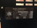
| Manufacturer | Beehive |
| Model | B100 |
| Lifetime | |
| Introduced | July, 1976 |
| Introductory Price | $1,495 |
| Communication | |
| Interfaces |
RS-232C, 20 mA current loop |
| Baud Rates | 75, 110, 150, 300, 600, 1000, 1200, 1800, 2000, 2400, 3600, 4800, 7200, 9600, 19200 |
| Display | |
| Size | 12-inch |
| Refresh Rates | 60 Hz, 50 Hz |
| Character Modes | |
| Resolutions | 80x24, 80x12 |
| Attributes |
Normal, Blink, Protected |
| Matrix | 5x7 |
| Cell | 7x9 |
| Firmware | |
| CPU | Discrete Logic |
| Code Chart | Beehive B100 |
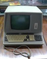
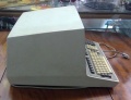
The Beehive B100 terminal was introduced in June, 1976 for $1,495.[1][2]
The design of the B100 was similar to the Lear Siegler ADM-3A and was created by engineers who left LSI to form Soroc Technology.[3]
The B100 includes the following features:
- Cursor control (up, down, left, right)
- Cursor home
- Cursor position absolute
- Clear from cursor to end of line
- Clear from cursor to end of screen
- Clear screen
- Insert mode
- Blink mode
- Format mode
- Protected fields
- Keyboard enable/disable
- Line send
- Page send
- Auxiliary page send
Normally the terminal operates in a "conversational mode" where keys are transmitted as soon as typed when the terminal is on-line. A switch at the rear of the terminal can put the terminal in "block" mode. In block mode, data is only transmitted when the SEND key is pressed. Format mode allows portions of the screen to be configured as protected. Protected portions of the screen are not transmitted when the SEND key is pressed. When format mode is combined with block mode transmission, the screen is typically configured as a "fill out form", with protected regions used to label the input fields on the form. The user can move the cursor from field to field, entering and editing the data displayed on the screen until correct. The SEND key is then used to transmit the entire unprotected contents to the computer.
Hardware Description
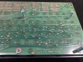
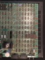
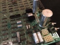
The Beehive B100 terminal is quite complex for a discrete logic design. The trend was towards microprocessor based designs in the period following the introduction of the B100. The B100 control circuitry is divided into two main sections: display refresh and receive/transmit functions.
Display Refresh
Display timing is driven by a cascade of counters, each divided down from the previous. The main timing chain (oscillator, dot position counter, character position counter, character height counter, and character line counter) defines the configuration of the display on the CRT. There are 30 lines, 6 of which are used for vertical retrace and 24 of which are used to display characters. The 30 lines are composed of 9 scans each. Each scan is composed of 96 character times, 80 for display and 16 for horizontal retrace. Each character block is composed of a 7x9 dot matrix field which contains a 5x7 character matrix for the displayed character.
Oscillator
The oscillator is crystal controlled with a frequency of 10.8864 MHz. Two 74H04's are connected in series by a 100 pF capacitor. Each 74H04 has a 1 Kohm feedback resistor around it. A 10.8864 MHz crystal is connected to the input of the first 74H04 to the output of the second. The output of the oscillator is buffered, inverted and fed to the Dot Position Counter.
Dot Position Counter
This divide-by-seven counter defines each of the seven dots required to compose one character. The outputs of this four stage counter are labeled DPC1, DPC2, DPC4 and DPC8. The counter actually presets to a count of 10, counts up through the overflow point at 15 to a count of zero, and then presets back to a count of 10. The Dot Position Counter output, DPC8, drives the Character Position Counter.
Character Position Counter
The Character Position Counter is composed of two binary type counters that define 96 character times, each being seven dots wide. The output of the Character Position Counter drives the Character Height Counter.
Character Height Counter
The Character Height Counter is a standard counter that defines 9 scans of 96 characters each, with each character being seven dots wide. The output of the Character Height Counter drives the Character Line Counter.
Character Line Counter
The Character Line Counter is a binary counter that starts at a count of zero and counts to a maximum of 29 for a total of 30 character lines. The final output of this counter runs at the vertical refresh rate.
Horizontal and Vertical Drive
The Horizontal Drive is started when the Character Position Counter leaves the video area of the scan and is active for the following 40 character times. The high active output of this flip-flop is sent to the monitor on pin 9 of connector J1.
The Vertical Drive is generated during the time that the Character Line Counter is decoding 26.
Cursor Location Counter
The Cursor Location Counter identifies the location of the cursor. This is a count made from the Cursor Line Counter, called CURL, and the Cursor Position Counter, called CURP. These two counters, in conjunction with the ROLL counter, are used to address the memory to determine the entry point of the next character. The cursor location counters are compared with the Character Position Counter and the Character Line Counter to generate the signal called CNTR CURSOR. This signal is used to generate the cursor displayed on the CRT. Also associated with the cursor location counters is the appropriate circuitry to move the cursor up, down, left, right, etc. A LINE FEED code causes the Cursor Line Counter to increment by one. A CARRAIGE RETURN code clears the Cursor Position Counter.
With the terminal operating in FORMAT MODE, when the cursor is incremented off the bottom line, the cursor automatically wraps around to the top of the display, i.e., the Cursor Line Counter is reset to zero. However, if the terminal is not in FORMAT MODE, the display scrolls whenever the cursor increments from a count of 23.
A scroll is initiated by any of 3 functions if activated when the cursor is on the last line of the display and the terminal is not in FORMAT MODE:
- LINE FEED or Ctrl+J
- CURSOR DOWN or ESC B
- if the cursor is on the last position of the last line:
- Cursor right
- Any displayable character
- Space
Memory
The page memory is arranged as 2048 9-bit words: 7 for character data, one for protect and one for blink. Of these 2048 words, 1920 are displayable. The program does not have the capability of displaying or writing into the remaining 128. In order to write data into the page memory from the receiver, the memory address is multiplexed over to the cursor location registers and the signal WRITE is generated. The UART is then reset and is capable of receiving the next character. The page memory output is sent to the character generator input buffer at the proper time to generate the displayable characters. The program has the capability of shutting down the screen refresh for any given to increase the operating time.
Character Generator
The Character Generator is a read-only memory (ROM) that is address by the character (in ASCII). The scan configuration of the character indicates the pattern desired on that scan. Five-bit dot patterns are generated which form a portion of a character. The output of the character generator is applied to the parallel-to-serial video shift register.
Video Shift Register
The paralle-to-serial Video Shift Register is loaded with data by the low-active signal, DPC8, and is clocked by the main oscillator output. The dots are shifted out, mixed with cursor information, and blanking signals, and applied to the monitor through the CONTRAST control as video information.
Transmit and Receive
Processing of received escape sequences is handled by a state machine implemented in a programmable logic array. The state machine has a small set of fixed-function registers for performing the various operations requested by the escape sequences. In some lengthy operations, access to the display memory by the display refresh circuitry may be disabled so the state machine can complete the requested operation without competing for access with the refresh circuitry. This has the effect that the screen will not display stored characters for as long as display refresh is disabled. At the end of the operation, display refresh access is enabled and the display of characters on screen is restored.
UART (Receiver)
Data can be received by the B100 from one of two sources: from the I/O interface into the receiver side of the UART, or from the keyboard through the transmit side of the UART to the receive side of the UART.
The UART is driven by a clock generated internally off the main counter chain. No separate oscillator is required. A rotary switch located on the back panel switches the clock rate for operation from 75 to 19200 baud. The time 16 clock is then applied to the transmitter and receiver of the UART.
The EIA line receiver receives data at RS 232C levels and gates them into the UART when the B100 is on-line. Through the same gating, data is brought from the transmit side of the UART. The data is brought into the UART where it is converted to parallel (seven bits) data.
UART (Transmit)
The keyboard data lines for bits 1 through 7 are applied to the transmit input data lines along with the seven BUS lines. Also coming from the keyboard circuit is a load signal which triggers the UART to initiate the transmission. As the UART receives the character for transmission, it performs the appropriate parity generation, provides one or two stop bits, divides the X16 clock to get the baud rate, and transmits the character. The character is applied through an EIA RS 232C interface to the computer or modem. Also coming from the UART is output data at a TTL level which is applied to the receiver side of the UART through the previously mentioned logic. The EIA interface includes a Data Terminal Ready signal which indicates the status of the B100 to the computer and a Request to Send signal which indicates that the terminal has data to send to the computer. The Clear to Send line coming from the computer is monitored at the EIA RS 232C interface levels. It is received by a line receiver which converts it to TTL levels and applies it to the UART clock control circuit to control transmission. An optional times 8 clock (TTL levels) is available as part of the interface. The BREAK key is on the keyboard and enables a timer which holds the transmit data line in a spacing condition for a predetermined period of time.
Block Send Circuit
The Block Send feature allows the operator to compose a message on the terminal screen and then, by depressing the SEND key, cause the terminal to send the entire message to the computer at the selected baud rate. The operation is as follows:
- Raise Request-to-Send
- When Clear-to-Send, send STX (002) header.
- Send data
- If FORMAT and END OF PROTECTED FIELD, send HT code (005).
- If not FORMAT and END OF LINE, send CR/LF sequence.
- When end of message, send ETX (003).
- Time out and drop Request-to-Send
Auxiliary Send Circuit
The Aux Send feature is identical to the Block Send except for two points:
- The message is transmitted out the AUX Port instead of the Main I/O Port.
- The delimiters sent at the start of message, end of unprotected field (135), end of line (134), and ETX (003) are selected from a different portion of the Block Send ROM.
Special Function
Sends a code sequence to the computer from the terminal. The code is instigated by pressing any one of the 16 function keys.
- An STX is transmitted (002)
- An Escape code (033)
- Code character (see ASCII Code Chart)
- And ends with an ETX (003)
Manx
Images

Advertisement


External Links
- Beehive B100, Deskthority
References
- ↑ "Few Products Announced for Large System Users", Computerworld, June 14, 1976, pg. 4
- ↑ "Beehive Designs Terminal For users on Budgets", Computerworld, July 5, 1976, pg. 16
- ↑ "Lear-Siegler Terminal". http://www.old-computers.com/site/header/terminal.asp. Retrieved March 15, 2012.
| This article is a stub. You can help the Terminals Wiki by expanding it. |